
Extension Planning Map Example: What to Show
A good extension planning map example makes one thing immediately clear: where the property is, exactly which land is included in the application, and how the proposed work relates to its surroundings. For a rear, side, or loft extension, the map is not usually the document that shows every construction detail. Its job is to provide accurate, licensed geographic context so the planning authority can identify the site without guesswork.
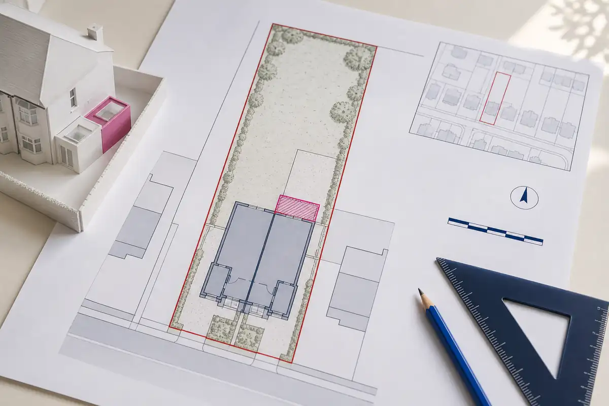
An extension planning map should make the proposal easy to place and understand. The location plan identifies the property in the wider area; the site plan or block plan shows the extension beside the house, boundaries, access and neighbouring land. Check the scale, red line, blue line and coverage against the local planning authority's current requirements.
What an extension planning map example should include
The exact drawing list varies, but location and site plans are commonly requested with existing and proposed floor plans and elevations. Each has its own job.
1. The location plan
The location plan shows the application site within the surrounding street or area. It should include enough roads, buildings and other recognisable features for somebody unfamiliar with the address to find the property. A north point, stated scale and clear application boundary are normally expected.
For many built-up properties, 1:1250 is a common location scale. A 1:2500 map covers more ground and may suit a rural property, large plot or site set back from a road. These are typical choices; follow the authority's validation list.
The application site is normally red. For a straightforward householder proposal, it often follows the residential boundary, but this is not a rule that the whole curtilage must always be included. The line should cover all land needed for the proposal, including access from the public highway where relevant, and not merely the extension footprint.
Other nearby land owned by the applicant may need to be outlined in blue when it is outside the application site. The blue line gives information about wider ownership; it does not add that land to the proposed development.
2. The site or block plan
The site plan, also called a block plan, shows how the extension relates to the house and nearby features. The guide to location plans and site plans explains why they are not interchangeable.
A site plan is commonly 1:500 or 1:200. A 1:500 plan shows more context. The technically larger, more detailed 1:200 scale shows the extension and boundaries more closely but covers less land. Some local authorities ask for householder block plans at 1:100 or 1:200, so use their checklist rather than assuming one scale.
The plan may need existing and proposed buildings, access, parking, gardens, neighbours and boundaries. Trees, hard surfaces, rights of way, walls or fences may matter where affected by the work.
The underlying Ordnance Survey mapping normally records existing mapped features. It will not automatically show an extension that has not been built. The proposed footprint must therefore be added clearly and must agree with the floor plans, elevations and dimensions elsewhere in the submission.
A practical example for a rear extension
Take a typical semi-detached house with a proposed single-storey rear extension. The 1:1250 location plan identifies the property within its street and places a red line around the application site. Nearby roads and houses give enough context to locate it.
The closer site plan shows the house, garden boundaries and rear extension. Its relationship with the neighbouring property and adjoining boundary should be clear. Show access, parking, trees or hard surfacing where relevant.
The site-plan footprint must match the proposed floor plan. If one drawing shows a full-width extension and another sets it away from a boundary, clarification may be needed. Dimensions and orientation should remain consistent.
Where the applicant owns an adjoining strip of land that is not part of the proposal, that land may need a blue line on the location plan. The blue line planning application boundary guide explains the usual ownership distinction.
A corner plot, listed building, sloping garden or extension near significant trees may need more information. Use the authority's list rather than copying another application.
Red line boundaries: the detail that causes most errors
The red line defines the planning application site. A frequent mistake is drawing it around only the proposed extension. That identifies the area of work but may not identify all the land to which the application relates.
Consider the whole property and its public-road connection. Where the application includes the house, garden and access, the boundary should reflect that. Check whether any new driveway, parking or drainage land also forms part of the site.
Do not include neighbouring land simply because it appears beside the site, and do not add all owned land automatically. Include land needed for the proposal; red and blue serve different purposes. See the red line boundary guide.
Boundary mistakes do happen when somebody is ordering a planning map for the first time. In Mr Miller's review, he explained that he accidentally ordered a plan without the red boundary. He telephoned UK Planning Maps, and the team corrected and resent it. It is a useful example of checking the finished file and asking for help, not a guarantee that another map or application will be accepted.
Ordnance Survey mapping does not prove legal ownership. Use the relevant title information and seek advice for an uncertain boundary, leasehold interest or shared access.
Choosing the right scale for your extension
Scale balances coverage and detail. A location plan needs context; a site plan needs enough detail for the extension without cropping relevant boundaries or neighbours.
For a normal street, 1:1250 often works well. For a rural house or large plot, 1:2500 may show access and landmarks better. The red line must remain visible.
At site level, 1:500 can show the house, garden, driveway and neighbours. A 1:200 plan suits close detail near a boundary. If the site does not fit, use another scale, larger sheet or additional drawing.
Check the PDF at its intended size. Print at 100% or actual size, not “fit to page”, which can alter scale. Retain the scale bar: it is useful for checking the output and some local authorities require it.
Common mistakes to avoid
If both maps are requested, submit both. A block plan may explain the extension but lack wider context; a location plan may identify the house without enough proposal detail.
The mapped base usually shows the current building. Outline and label the extension clearly on the proposed plan, using lines readable on screen and in print.
Keep red complete and use blue only where needed. Lines must not hide useful details. A wide map can shrink the boundary; a tight crop can remove the street or access.
Screenshots and old plans may lack scale, north, current detail or suitable reproduction rights. Use current mapping supplied with the appropriate copyright and licence information for its intended purpose. Ordnance Survey mapping is a common planning base in Great Britain, but it is not universally mandatory. UK Planning Maps covers England, Scotland and Wales, not Northern Ireland, and applicants should check what their authority accepts.
Do not upload an early plan. Name files clearly, such as Location Plan, Existing Site Plan or Proposed Site Plan, and open uploaded copies to confirm them.
Finally, compare the maps with the application form, ownership certificate, floor plans and elevations. The address, orientation, extension position, access and application boundary should tell the same story throughout.
Creating your plan without starting from scratch
Check validation requirements and gather the address or coordinates, plan type, scale and boundary. Compare buildings, roads and access rather than relying only on a postcode.
Choose the location plan, site plan or both, then position the map so the whole relevant site and enough surroundings are visible. Draw the red line carefully, add blue where required and check the preview before paying.
After a completed online order, the map is available to download from the UK Planning Maps website immediately; an email copy can take up to 20 minutes. Open the PDF and review scale, north, coverage and boundaries, then save an untouched copy. If a designer needs editable mapping, confirm whether CAD is more suitable.
An extension planning map example is a checklist, not a template to copy blindly. Requirements vary. A clear map helps the authority identify the site and understand the work, but it cannot guarantee that an application will be validated or approved. Check the complete submission against the current local requirements.
Ready to Get Your OS Plans?
Every plan is instantly downloadable, Planning Portal‑compliant, and includes all required elements. Get your plan now and submit your application with confidence.