
DXF Maps With Height Data for Accurate Site Design
A site can look level on a standard base map and still create expensive design problems. A driveway may need more excavation than expected, surface water may run toward a building, or a proposed extension may sit above or below the surrounding ground. DXF maps with height data give designers a practical starting point for seeing those changes in level before drawings move too far forward.
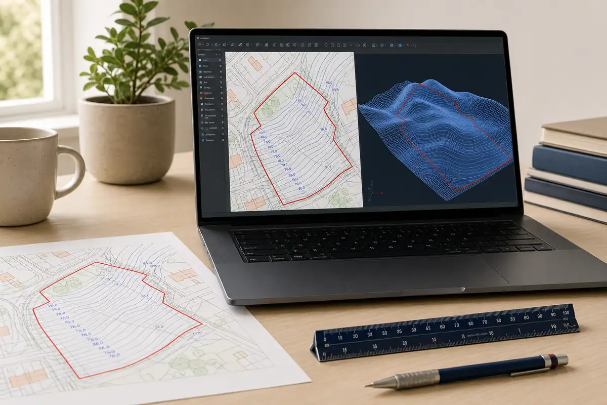
For architects, surveyors, developers, and self-builders working on UK land, height information can make early feasibility work faster and more informed. It is particularly useful where a plot slopes, boundaries cross uneven ground, access is tight, or drainage and retaining walls may affect cost. The key is knowing what the data shows, what it does not show, and when a measured site survey is still needed.
What a DXF map with height data contains
DXF is a widely used CAD file format. It allows mapping information to be opened, viewed, and used in software such as AutoCAD and other CAD platforms. Instead of tracing a PDF plan or rebuilding a site base from scratch, a DXF file places mapping features into a usable drawing environment.
When height data is included, the file adds an elevation dimension to the plan view. Depending on the dataset and area, this may be represented through contours, spot heights, height points, or a terrain model that can be used to understand the shape of the land. A contour joins points at the same elevation. Where contours sit close together, the ground is steeper; where they are further apart, the land changes level more gradually.
That makes the file more useful than a flat location or site plan for work involving levels. You can assess the direction of fall, identify higher and lower parts of a site, and begin coordinating a building footprint with likely access and drainage constraints.
Height data should not be confused with building heights. Terrain height data describes ground levels. It does not automatically provide verified ridge heights, eaves levels, underground services, tree canopy measurements, or the precise dimensions of existing structures.
When height data is useful in site design
A DXF file with terrain information is most valuable when the design needs to respond to the land rather than simply sit on it. On a relatively flat urban plot, standard CAD mapping may be enough for an initial application drawing. On a sloping garden, rural parcel, former agricultural land, or site with a long access route, levels can influence almost every early decision.
For an extension, height data can help establish whether a new floor level, patio, steps, or drainage route may need closer attention. For a new dwelling or conversion, it can inform initial massing, likely cut-and-fill requirements, and how the proposal may appear from neighboring land. For a larger development, it can support early discussions around road gradients, accessible routes, surface water management, and plot layout.
It also helps teams communicate. A CAD technician can place the mapping beneath concept drawings, while a designer can review slopes without working from disconnected files. For repeat users, this saves time at the stage when several options are often being tested.
Height data is not a substitute for a topographic survey
This distinction matters. Mapping-based height data is excellent for preliminary assessment, broad site understanding, and early design coordination. It may not have the density, accuracy, currency, or site-specific detail required for construction design, engineering calculations, boundary work, or formal level verification.
A professional topographic survey is normally the right next step where decisions depend on precise levels. This may include setting finished floor levels, calculating excavation volumes, designing retaining structures, specifying drainage falls, assessing flood risk, or producing setting-out information for contractors.
It also depends on the site. Dense vegetation, recent earthworks, walls, embankments, and small changes in level can all matter in a way that generalized terrain data may not fully capture. If a difference of a few inches could change the design or budget, obtain a survey with a stated accuracy specification and coordinate system.
The sensible approach is to use the available data in proportion to the decision being made. Use DXF terrain mapping to assess options early. Use a measured survey when the project moves into detailed design, technical approval, or construction.
Choosing DXF maps with height data
Before ordering, confirm that the product is suitable for both your area and your intended use. Start with the site boundary and the amount of surrounding land needed. A file that only covers the footprint may be too limited for assessing approach roads, drainage outfalls, neighboring ground levels, or the wider visual relationship of a proposal.
Check the coordinate reference system and the vertical datum used by the data. Your architect, engineer, or surveyor may need the file in a particular coordinate system so it aligns with survey information and other project drawings. Mixing files with different references can create apparent offsets or incorrect level comparisons.
You should also ask how elevations are presented. Contours may be ideal for quickly reading a broad slope, while point data or a terrain surface can be more useful for 3D modeling. The right format depends on the software and the task. A simple planning sketch may only need contours; an early earthworks exercise may benefit from more detailed terrain information.
A useful order brief should cover these five points:
- the exact site area and surrounding coverage required
- the CAD software and DXF version your team uses
- the coordinate system required for the project
- whether contours, points, or a terrain model are needed
- the design purpose, such as feasibility, drainage, access, or 3D massing
Giving this information at the outset reduces rework and helps ensure the mapping can be placed straight into the drawing package.
How to use the file effectively
Once the DXF is open in CAD software, keep the terrain data on its own layer or set of layers. This makes it easier to switch levels on and off as the drawing develops. Label the source, date, coordinate reference, and any stated data limitations in the drawing record so other consultants understand what they are using.
At the concept stage, use the contours or elevation points to test the siting of the proposed building. Consider where entrances meet the ground, whether a level threshold is realistic, and how vehicles and pedestrians would move through the site. A building positioned only a short distance away can have a very different relationship with the slope.
For drainage, start by identifying the natural direction of fall. This does not replace a drainage design, but it can highlight obvious questions early: Is there likely to be a low point near the building? Could water be directed away from the structure? Will an access route cross the fall of the land? These are cheaper questions to answer before a layout becomes fixed.
For 3D work, the data can provide a base terrain surface for initial massing studies. This can help show how a proposed building relates to the site from nearby viewpoints. Be clear in any presentation that the terrain model is based on supplied mapping data and is not a detailed measured survey where precise levels are critical.
Planning drawings and CAD terrain data serve different jobs
A planning application normally requires a location plan and, in many cases, a site or block plan at the scale requested by the local planning authority. These plans identify the site, surrounding context, boundaries, and proposed works. They are not usually intended to replace technical level drawings.
DXF terrain information works alongside those documents. It supports the design process that leads to a better-informed application, particularly on sloping or complex land. Later, the same base may help coordinate drawings between the architect, drainage engineer, highways consultant, and surveyor.
UK Planning Maps can provide licensed mapping in planning scales and CAD or terrain-data formats, helping teams obtain the appropriate base information without separately sourcing licensed mapping. For planning submission plans, always check the local authority's stated scale, coverage, and annotation requirements. For technical drawings, confirm the level of accuracy required by the consultant who will rely on them.
Common mistakes to avoid
The most common mistake is treating contours as a final answer rather than an early design input. Another is assuming that a site plan drawn over a terrain base automatically proves levels are acceptable. It does not. The design still needs suitable surveys, calculations, and approvals where required.
Avoid altering elevation values without recording the change, or mixing terrain information from different sources without checking references. Also make sure the drawing units are correct. A file in meters opened as feet, or vice versa, can quickly create misleading results.
Finally, do not wait until the technical stage to look at the slope. If levels are likely to affect access, drainage, foundations, or the appearance of a proposal, bring them into the first layout discussion. A well-chosen DXF terrain base will not remove every site risk, but it gives your project team a clearer ground to work from before the costly decisions begin.
Ready to Get Your OS Plans?
Every plan is instantly downloadable, Planning Portal‑compliant, and includes all required elements. Get your plan now and submit your application with confidence.